
The tension screw No. 70 is a left hand screw, and operates the reverse of ordinary screws. With that the tension can be increased or lessened at pleasure. To increase the tension, turn the screw-driver No. 198, shown above.
To decrease the tension, turn the screw in the opposite direction.
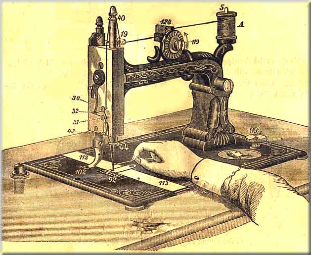
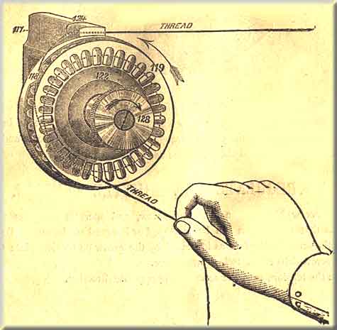
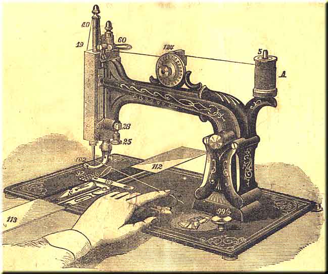
Use 60 cotton and a No. 1 needle in learning. Place the spool of cotton "A" on the spool-pin at No. 5, draw the thread into the slot at No. 124 in the top of the tension stand; thence into the V-shaped groove of the tension wheel at point 118 (see Fig. 11, page 12), and twice around the wheel in the direction indicated by the arrow; thence through the thread controller No. 19, and into the slot on the top of the needle bar No. 40, and downwards under thread guide-pin No. 38; thence through the hook on the end of the take-up No. 32, and back over thread guide-pin No. 37; thence through the curved hook No. 44 at the bottom of the needle bar, and lastly through the eye of the needle, as shown in Fig. 10, page 12.
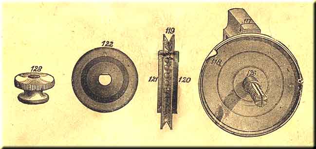
Take off the thumb nut 128, then the tension nut washer 122, and lastly the tension wheel 119, and put half a drop of oil on the screw stud directly at 126.
Great care must be taken to get no oil on the cloth washers 120 and 121 on the sides of the tension wheel.
In re[placing the wheel, always put the black cloth washer 120 back. To replace the nut washer 122, it will be observed that one side of the hole is flat, which must be put on to fit the flat side of the screw stud 126, then put on the thumb nut 128. Once a month is often enough to oil the tension.
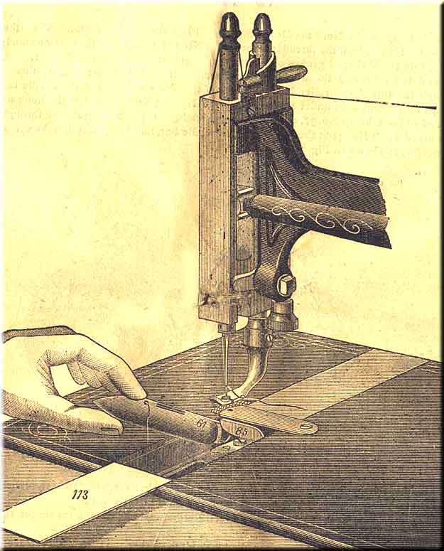
Raise the needle bar to its highest point, withdraw the front slide 113, take hold of the shuttle and slide the heel along on the bottom of the race, holding the point high enough to allow the hook on the heel to pass under the end of the driver No. 85; then let it drop into its place, as shown in Fig. 16, page 16.
NOTE -- Draw the thread through the eye of the needle and through the hole in the side of the shuttle, so as to leave the ends about three inches long.
Withdraw front slide 113; hold the end of upper thread slack with the left hand; turn the driving-wheel with the right hand until the needle passes down.
If the needle is set properly a loop will be formed by the upper thread in the shuttle race (see Fig. 16, page 16), through which the shuttle will pass, and the needle, in its ascent, will draw the lower or shuttle thread up through the hole in the throat plate No. 109.